Computational Fluid Dynamics for Predicting Performance Through Ansys.Cfx In Hydrocyclone
Dinesh Agrawal1, Mahendra Kumar Malviya2, Vibha Agrawal3
1Mechanical, Govt. Polytechnic College, Morena, (M.P.), India
2Lecturer, Govt. Polytechnic College, Betul, (M.P.), India
3Gyan Ganga Institute of Technology and Management, Bhopal, (M.P.), India
Article Publishing History
Article Received on :
Article Accepted on :
Article Published : 12 Aug 2014
Article Metrics
ABSTRACT:
Thehydro cyclone is an important and popular industrial apparatus to separate by centrifugal action disperse solid particles from a liquid suspension fed to it. It has been widely used in industry, particularly in the mineral and chemical processing industry because of its simplicity in design and operation, high capacity, low maintenance and operating cost as well as its small physical size. In general how a hydro cyclone works is included, providing a background to discuss a process and hydro cyclone geometry variables. The CFD technique popularly in process design and predicting equipment performance of hydro cyclone under a wide range of geometric and operating condition by using ANSYS.CFX; it also offers an effective way of design and modeling of hydro cyclone.
KEYWORDS:
CFD(computational fluid dynamics); hydro cyclone; underflow; overflow; ANSYS
Copy the following to cite this article:
Agrawal D, Malviya M. K, Agrawal V. Computational Fluid Dynamics for Predicting Performance Through Ansys.Cfx In Hydrocyclone. Orient. J. Comp. Sci. and Technol;7(2)
|
Copy the following to cite this URL:
Agrawal D, Malviya M. K, Agrawal V. Computational Fluid Dynamics for Predicting Performance Through Ansys.Cfx In Hydrocyclone. Orient. J. Comp. Sci. and Technol;7(2). Available from: http://www.computerscijournal.org/?p=1156
|
Introduction
Cyclone separators are devices that utilize centrifugal force to separate material of different densities, size and shape. The hydro cyclone as a subcategory of cyclone – is a cyclone separators used for separation of particles in immiscible droplets from liquid. The separation action of hydro cyclone is based on the effect of centrifugal force created within the cyclone body. In contrast to sedimenting centrifuges however hydro cyclone no rotating parts. Solid liquid separation in hydro cyclone is never complete. There are some fine solids escaping with the overflow and there is certainly liquid discharging with the solid through the underflow. The ability to separate solid from another in clarification duties is related to the sharpness to cut.
Application of hydro cyclone industry falls into several broad category. Clarification is to produce clear overflow, thickening to produce thick underflow, classification is for solid-solid separation by particle size, sorting is for solid-solid separation for solid density, counter-current washing for washing of solid by re-slurring, liquid-liquid separation, liquid degassing and particle size measurement. Many existing applications of hydro cyclone are in mineral processing, chemical industry and also in oil industry.
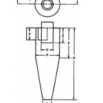
Hydro cyclone consisting of conical shaped vessel, open at its apex or underflow joint to a cylindrical section which has tangential feed at inlet. The top of the cylindrical section is closed with the plate through which passes an axially mounted overflow pipe. The pipe is extended into the body of cyclone by short, removable section known as the vortex finder, which prevents the short-circuiting of the feed directly into the overflow.
The flow pattern and the normal design of the cyclone is spiral. Fluid on entry commences downward flow in outer region of the outer cyclone body. This combines with rotational motion to which it is constraint creates the outward spiral. Existing top of central outlet and inability in flow rate condition (under normal feed pressure), for all liquids to leave at cone apex, Outlet assists the inward migration of some of the fluid from the external downward moving mass. The amount of the inward migration increases as the cone apex neared and the fluid which flows in the migratory stream ultimately reverses its vertical velocity direction and flow upward to the cyclone overflow outlet via the vortex finder. Since once again it is the same time rotation the result is in a spiral. Motion of the reversible of the flow and the existence of the inner and outer spiral can lead to misunderstanding and mistaken belief that the spirals rotate in the opposite direction. This obviously cannot be true. The reversals applied to the vertical component of the velocity and the spiral rotates in the same circular direction. The reversals of the flow was explained in terms of the requirement that all of the fluid should not be passed in the same direction out of the cone apex opening. The word assists was however under deliberately since reversals does not take place in the force vortex where there are no constraint caused by vessel design.
The performance of a hydro cyclone is generally characterized by the size of particles for which separation is successful. Specifically, D50 is the particle size for which one-half of the injected particles escape through the overflow. A smaller value of D50 characterizes a more effective hydro cyclone in general, though pressure drop is also a concern and different hydro cyclones are designed for different application. As such still scope for modeling and analysis particle separation characteristics of hydro cyclone and for validation of the results.
Literature review
The available theories related to hydro cyclones can be classified according to their underlying principles into five groups
- Simple fundamental theories mainly include two theories namely Equilibrium orbit theory (crier 1950 and Drissen 1951, Bradely and Pulling 1959 and Bradely, 1965) and Residence time theory (Rietma 1961, Trawinski 1969 and Kutepov et. al. 1977-78, Holland-Batt 1980). The equilibrium orbit theory based on the concept of equilibrium radius. According to this concept particle of the given size attain an equilibrium radial orbit position in a cyclone where settling velocity is equal to the radial velocity of the liquid.
- The residence time theory assumes non equilibrium condition and considers whether a particle will reach the cyclone wall in the residence time available. These theories, however take no or little account of the flow ratio (or size of the underflow orifice), of the feed concentration and of the feed size distribution.
- The crowding theory (Fahlstrom 1960, Bloor et al 1980 and Leverack 1980) explains the strong effect of the size of the underflow orifice on the cyclone performance in some cases.
- The fluid flow models basically deals with the solving Navier-Stokes equations to understand the flow behavior of slurries inside cyclones of various designs. These models include analytical flow, numerical simulation, turbulence two-phase flow and multi-phase flow models. These models help understanding of flow patterns inside the cyclone and of the particle trajectories, including the boundary layer flow, the short circuit flow, and internal eddies. However, the models develop so far are applicable only for low feed solid concentration.
- The all-embracing empirical, based mostly on regression analysis of the measured data, applicable only to specific systems tested.
Nikkam Suresh et. Al (1966) presents a performance model for water-only-gravity separator treating coal. The conventional method for predicting the performance of coal cleaning unit is by plotting a generalized distribution curve, which is cumbersome. It describes tromp curve using a Rosin – Rammler type of equation for estimating performance. Experiments carried out on laboratory water-only cyclone to produce Tromp curve of widely varying nature.
D.P. Patil, K.V. Bhaskar (1996), presents removal of graphite from lead rougher concentrate using water-only cyclone. In the present study the possibility of using water -only cyclone to separate graphite from lead rougher is analyses on the basis of investigations carried out result indicates that it is possible to get a lead concentrate of 39% lead with 2.6% graphite at a recovery of 45% from a feed assessing 19.6% lead and 9.8% graphite.
Wieslaw S. Blaschke states in book New Trends in Coal preparation Technologies and equipments – (1995); on page 413 that water-only cyclone applies for fine coal treatment as well as characteristics for spiral concentrator and rotation machines for slurries. The present time there are no generalized characteristics for the separation efficiency jigs, dense medium cyclone and water-only cyclone adjusted to the treatment of the slurries both bench and industrial scale test of cleaning process water-only cyclone (diameter 125-150 mm) conducted in GB as well as those carried out in Germans and Canada with dense medium cyclone for coal sized 0.7 – 0.1 or 0.5-0.1 mm and finer, bring significant in recognizing the influence of particular technical construction parameter.
V. K. Kalyani, T. Gouri Charan, et. al. (2008), presents coal fine beneficiations studies on a bench-scale water-only cyclone using artificial neural network. Study highlighted the result of a case study of beneficiations of high ash fine coal, using a water-only cyclone. The influence of the two critical design variables viz., cyclone length and solid concentration on which the cyclone performance and process yield (%) depends to great extent, is described. Further, based on the experimental data of a water-only cyclone of varying length used for below 3mm coal beneficiation study, an attempt has only been made to develop 3 layer feed – forward artificial neural network (ANN) model, which is inherently trained using an error-back algorithm. The ANN model are qualitative and quantitative agreement with the experimental observations, their by validating the applicability and the accuracy of the developed ANN model.
Computational Fluid Dynamics modeling
Mathematical models of hydro-cyclone flow are based on strongly coupled elliptical partial differential equations of mass and momentum conservation which are difficult to solve. Hence, studies on hydro-cyclones are still largely based on experiments. The empirical models can be applied only to simple hydro-cyclone geometry with tangential fluid (water) inlets. These models have been successful in many specific industrial applications but use of these empirical models for other hydro-cyclone inlet configurations is uncertain. Traditional methods may not always lead to best design for optimal performance as it is difficult to develop suitable empirical models for in coaxial hydro-cyclone on basis of pilot scale equipment. This study tries to lead to the best design for optimal performance of hydro cyclone using CFD.
CFD has become a useful tool to understand the complex flow structures typical of hydro-cyclones by excluding the need of costly experimental studies. This work presents a numerical study using automated CFD tools to analyze dilute phase incoalrial hydro-cyclone of standard and non-standard dimensions. In this work, a CFD analysis of hydro-cyclone for coal separation is proposed to be done using FLUENT software. A higher order Reynolds stress turbulence model will be used to study the velocity profiles. The air core will be modeled using this tool and as a result the throttling effect of this on the underflow and overflow orifices will be defined. The flow-splits from an actual hydro cyclone test will be compared to predicted flows from the model at different vortex finder sizes. A CFD tool also provides the ability to track the path of various size particles along the internal hydro cyclone flow field. The particle recovery curve from the CFD model will be compared with the actual hydro cyclone performance measured in a controlled test. The CFD model predictions to different vortex finder sizes and the addition of other hydro cyclone geometry will be studied. The CFD model will also provide a means to evaluate the effect of design changes on component wear. The tool will be used to keep track of the number, angle and magnitude of particle collisions on the hydro cyclone internal surface.
ANSYS CFX
ANSYS CFX software is a high-performance, general purpose fluid dynamics program that has been applied to solve wide-ranging fluid flow problems. The ANSYS CFD technology encompasses two well-established and widely-used CFD tools, ANSYS CFX and ANSYS FLUENT, which have been integrated into the ANSYS Workbench. Both of these world-leading general-purpose fluid dynamics products can be used to solve the majority of fluid dynamics problems . It offers a comprehensive range of physical models that can be applied to a broad range of industries and applications, with extensive capabilities for customization and automation.
The ANSYS CFX product allows engineers to test systems in a virtual environment. The scalable program has been applied to the simulation of water flowing past ship hulls, gas turbine engines (including the compressors, combustion chamber, turbines and afterburners), aircraft aerodynamics, pumps, fans, HVAC systems, mixing vessels, hydrocyclones, vacuum cleaners, and more.
A Finite Volume Method
Finite volume methods are essentially a generalization of the finite – difference method but use the integral form of the governing equations of flow, rather than their differential form. This gives greater flexibility in handling complex domains, as the finite volumes need not to be regular. This approach too has some problems, the main one being that the staggered grid with non-coinciding pressure and velocity grid points – traditionally used by finite difference solvers to avoid pressure – velocity decoupling – is difficult and computationally expensive to use in complex geometries. Thus, there has been considerable interest in the last two decades in developing algorithms for fluid flow computations which can be applied on non- staggered non-orthogonal grids, without transformation of the domain and governing equations.
A finite volume method on a non-staggered nonorthogonal grid, applicable to complex geometries, will be discussed. However, for the sake of clarity and simplicity, this general case will be introduced later in the chapter after discussing the method applied to orthogonal Cartesian grids (which can be used for suitable problems of simple geometry).
Governing Equations
The Navier – Stokes equations for laminar flow in an arbitrary domain of volume V bounded by a closed surface S can be expressed in the following general convection – diffusion-source integral form:
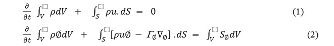
Where the fluid density, u is is the fluid velocity with components u, v, w, in the x, y, z directions respectively, is the diffusion coefficient (e.g., viscosity in the momentum equation) and is the volumetric source term. In this formulation we work with Cartesian components of velocity. So can be the three Cartesian components of velocity u, v, w, as well as any scalar e.g., temperature, T, which needs to be determined.
For incompressible flow of a Newtonian fluid, the equations take the form:
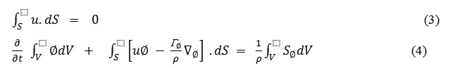
Where Equation 4 represents at least three separate equation for = u, v and w with
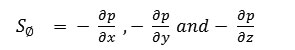
Respectively, that constitute the Navier – Stokes equations as well as others concerning temperature (T) and species concentrations, if required.
Approximations in the Discretization Technique
Discretization is the process by which the integral equation, having infinite continuum values throughout some domain, is converted into set of linear algebraic equations for values at centroid of the CVs. The integral conservation equations 3 and 4 are applicable not just to the entire solution domain but to each CV as well. The finite volume method uses these equations for each CV:
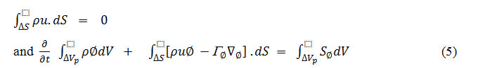
if we sum the equations for all CVs we obtain the global conservation equations 3 and 4, since surface integrals over inner CV faces cancel out. Thus global conservation is built into the method and this provides one to its principal advantages. As a result of the finite volume discretization procedure one obtains an algebraic equation for each CV, in which the centroid value and a number of neighbouring nodal values (.) appear. But this requires approximation at the two stages discussed separately in the following subsections.
Methodology
The conservation equations of mass, momentum and turbulence are solved using a finite volume method in order to determine the single-phase liquid velocity for comparison against the experimental data. It is not possible to arrive at a solution with these equations using analytical approaches; consequently ANSYS-CFX (release 11.0) is to be used to solve them on structured and unstructured grids. Rhie and Chow (1983) interpolation will be used to avoid chequer-board oscillations in the flow field.
Coupling between velocity and pressure is handled implicitly by a coupled solver. Advection terms are discretized using the “High Resolution Scheme” which is second-order accurate. The air core will be imposed as a free-slip boundary condition along the centre of the hydro cyclone, the width of which is derived from the experiments of Monredon et. al. (1992). As a normal CFD practice and a strategy to save computational time, the converged results of the k-ε model was used as an initial guess for the SST model and these results were then used for SST with curvature correction. The converged results from the turbulence model is not good enough to start the solution process of the SSG model, thereby LRR-IP (a simpler Reynolds Stress model in ANSYS CFX) will be run and its results will be used as an initial guess for the SSG model. Scalable wall functions within ANSYS CFX were used for k-ε turbulence model, while automatic wall functions were used for SST and its variants and SSG.
For the hexahedral meshes the y+ values were typically between 2-400, while for the tetrahedral/prism meshes the values were typically ranges from 7-200. CFD analysis is proposed to be done by segregated solver algorithm that solves the governing equations sequentially. In this approach, a single variable field is solved by considering all cells at the same time and the process continues for remaining variables.
General conservation (transport) equation for mass, momentum, energy, etc., are discretized into algebraic equations that can be solved numerically. The non-linear governing equations are linearized to produce a system of equations for the dependent variables in every computational cell. The resultant linear system is then solved to yield an updated flow-field solution.
Analysis of different turbulence models will be carried out for a turbulent flow inside a 75mm diameter hydro cyclone. Four different turbulence models will be tested of which three will belong to the two-equation model class and one to the Reynolds Stress class. ANSYS-CFX (release 11.0) will be used to solve the governing set of partial differential equations for flow and turbulence.
Experimental results of Monredon et al., (1994) will be used to compare the numerical findings. Mesh independency tests will be carried out to minimize any errors caused due to the underlying mesh. In addition to this, hexahedral and tetrahedral/prism meshes will be compared against each other to check the performance of each mesh type in capturing the flow physics within a hydro cyclone.
3D standard hydro-cyclone are developed by Pro-E software and exported to Gambit software for further refinement and discretization (mesh generation) of solution domain. Hexahedral mesh elements are preferred for a hydro-hydro-cyclone analysis by CFD because these are less diffusive than mesh element of other shapes. Discretization facilitates the field distribution of dependent variables subject to boundary conditions that define the specific problems. Computational domain using structured and unstructured grid schemes will be used. Structured meshes are typically easier to compute with but may require more elements or complex-shaped elements. In this work mixed grids have also been used for two hydro-cyclone models.
Conclusion
Velocity inlet boundary conditions are used to define the flow velocity at flow inlets. In this work turbulence intensity is proposed to be specified at the hydro-cyclone inlet. Pressure outlet boundary conditions are used to define the static pressure at flow outlets.
The results of CFD analysis are validated with experimental results from field study and numerical results available in literature.
References
- Chakraborti N. and Miller J.D. – Fluid Flow in Hydrocyclone. A critical review, Mineral Processing and Extractive Metallurgy Review, Vol. 11, pp. 211-244, (1992).
CrossRef
- Ding Feng et. al., applied mechanics and materials, 130-134, 3640, CFD Analysis of two-phase flow in a solid-liquid hydro cyclone, (2011).
- Madsen H. J., Thorstensen J. H., Salimi P., Hassing N. H., Rusass J., “Prediction of the performance of gas cyclone”, 2nd CFDS International User Conference, Pittsburg, USA, 211-227, (1994).
- Monredon, T. C., Hsieh, K. T. and Rajamani, R. K.. “Fluid flow model of the hydro cyclones: an investigation of device dimensions”, International Journal of Mineral Processing, 35, 65-83, (1992).
CrossRef
- Stephens D.W. and Mohanarangam K., turbulence model analysis of flow inside a hydro cycloneSeventh International Conference on CFD in the Minerals and Process Industries CSIRO, Melbourne, Australia 9-11 December (2009).
- E. J. O’Brien and Sherpeta, water-only cyclone: Their Function and performance, coal Age, Vol. 81, pp. 110-115 (1976).
- Fahlstrom P. H., Proceedings of Mineral Processing Congress, Inst. Mining and Metallurgy, pp. 632-643, (1960).
- Govindarajan, B., Modelling Studies on Vorsyl separator and Heavy medium Cyclone, Ph.D. Thesis, Indian School of Mines, Dhanbad, (1991).
- Kelsall, D.F. – A Study of Motion of Solid Particles in a Hydraulic Hydro cyclone – Trans. Inst., Chem. Engg. Vol. 30, pp. 87-108, (1952).
- Majumdar, A.K. and Baranwal J.P., – Modelling of enhanced gravity concentrators – present status, Mineral Processing and Extractive metal. Rev., 27: 1-26, (2006).
CrossRef
- Majumdar, A.K. and Baranwal J.P., Tiwari V., – separation characteristics of coal fines in a Knelson concentrator – A hydrodynamic approach, Coal preparation, 27: 126-137, (2007).
- Nikkam Suresh, Vanangamudi M., and Rao T. C., A performance Model for water-only cyclone Gravity Separators Treating Coal, Fuel, Vol. 75, pp. 851-854 (1996).
CrossRef
- Rietma K – Performance and Design of Hydro cyclones, Chemical Engg. Science, Vol. 15, September, pp. 298-325, (1961).
- Shah. H., Majumdar, A.K. and Baranwal J.P., – Developed of water split model for a 76mm Hydro cyclone, Mineral Engg. Vol. 19, Issue 1, January, pages 102-104, (2006).
- T. Gouri Charan, studies on the effect of some design and operating parameters of water-only cyclone for beneficiation of coal crushed to 3mm, M. Tech Thesis, Department of Fuel and Mineral Engineering, Indian school of Mines University, Dhanabad, India (1995)
- Verghese, P.A. and Rao, T.C., Modelling of a 76mm diameter Dense Medium Cyclone, Coal Preparation, Vol. 15, 71-91, (1994).
CrossRef
- Visman J., Integrated water-only cyclone plants for coal preparation, CIM Bull., Vol. 61, pp. 74-79 (1968).

This work is licensed under a Creative Commons Attribution 4.0 International License.