Real Time Depth Hole Filling using Kinect Sensor and Depth Extract from Stereo Images
Kapil Raviya1* , Ved Vyas Dwivedi2, Ashish Kothari3 and Gunvantsinh Gohil4
1College of Agricultural Engineering and Technology, Electronics Communication Engineering, Junagadh Agricultural University, Gujarat, India
2C. U. Shah University, Pro- Vice Chancellor, Wadhwan City, Gujarat, India
3Electronics Communication Engineering, Atmiya Institute of technology and Science, Gujarat technological university, Gujarat, India
4College of Agricultural Engineering and Technology, Junagadh Agricultural University, Gujarat, India
Corresponding Author’s Email: raviyakapil@gmail.com
DOI : http://dx.doi.org/10.13005/ojcst12.03.06
Article Publishing History
Article Received on : 29/06/2019
Article Accepted on : 30/09/2019
Article Published : 01 Oct 2019
Article Metrics
ABSTRACT:
The researcher have suggested real time depth based on frequency domain hole filling. It get better quality of depth sequence generated by sensor. This method is capable to produce high feature depth video which can be quite useful in improving the performance of various applications of Microsoft Kinect such as obstacle detection and avoidance, facial tracking, gesture recognition, pose estimation and skeletal. For stereo matching approach images depth extraction is the hybrid (Combination of Morphological Operation) mathematical algorithm. There are few step like color conversion, block matching, guided filtering, minimum disparity assignment design, mathematical perimeter, zero depth assignment, combination of hole filling and permutation of morphological operator and last nonlinear spatial filtering. Our algorithm is produce smooth, reliable, noise less and efficient depth map. The evaluation parameter such as Structure Similarity Index Map (SSIM), Peak Signal to Noise Ratio (PSNR) and Mean Square Error (MSE) measure the results for proportional analysis.
KEYWORDS:
Depth; Disparity; 3-Dimension; Guided Filter; Kinect; Morphological Filter; Stereo Matching; Warp; Zero Depth
Copy the following to cite this article:
Raviya K, Dwivedi V. V, Kothari A, Gohil G. Real Time Depth Hole Filling using Kinect Sensor and Depth Extract from Stereo Images. Orient. J. Comp. Sci. and Technol; 12(3).
|
Copy the following to cite this URL:
Raviya K, Dwivedi V. V, Kothari A, Gohil G. Real Time Depth Hole Filling using Kinect Sensor and Depth Extract from Stereo Images. Orient. J. Comp. Sci. and Technol; 12(3). Available from: https://bit.ly/2muSm61
|
Introduction
Kinect sensor is able to generate color and
depth images at the equal time at a speed of thirty frames per Second. Depth
data are used in 3-D vision and robotic applications. These applications are 3-D
television, 3-D communication, object detection, gaming industry and gesture
recognition for controlling devices. The
attractiveness of the Kinect camera can be qualified to its lower cost and the
real-time depth map making capacity. Kinect sensor is also known as RGB-D
camera. This camera is suffering with some problems while producing depth maps.
In this map large number of noise and holes are present. Therefore our
algorithm is efficient explanation to develop the sensor outcomes. Stereo
matching algorithms are reconstructed 3D scenes through matching multiple
images taken from slightly different viewpoints. The important task in machine
vision field is defining of 3D data from images. Stereo matching algorithms are
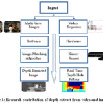
important to decide correspondences between the two views.1, 2 In this research we have developed two
algorithms namely real time depth hole filling and stereo matching method. Figure
1 shows functional block diagram of the research contribution. Objectives of
the research are as under;
To fill the hole for real time depth from
video sequences captured by Kinect sensor
To obtain depth map for multi view images
based on stereo matching algorithm
To analyze the results with the use of
qualitative parameters such as PSNR, MSE, SSIM.
Hole Filling
Using Kinect Sensing Device
Kinect camera consists of a RGB camera which
gives the RGB arrays output. The depth camera and the four microphone array are
capable to give the depth data and audio signal at the same time. Depth image,
color image, and audio streams are synchronized on primesense PS1080 System on
Chip-SoC. Depth is calculated from IR camera and IR projector. Infrared- IR
projector transmits the IR light in the form of speckle dot on the scene and
the IR camera captures the reflected IR speckles. One camera and one IR
transmitter provides input for the depth map 320×240 pixels resolution while
the third camera detects the human visual spectrum at 640×480 pixels resolution.3,
4
The input to the kinect map is raw depth
sequences. The filling of holes, object boundary rectification and alignment of
the pixel with color image is the vision of improvement of the depth map. First
step of implementation is image registration known as depth video
preprocessing. We set the trigger repeat, frame grab interval, total number of
frame acquired, resize the frame and continuously update the real time result.
It constructs a video sequence as an input object from the device and set the
port number. Color and depth cameras are available through specific port number
1 and 2 respectively. The frame grab interval identify how frequently to obtain
frame from video sequences. It is used to specify the interval so synchronize
the frame with mathematical process. It is measured in number of frames not in
time. If we define the interval value of five then every fifth frame is
acquired from video sequence. Trigger repeat property is executed every time
until the stop function or error occurs.
Depth renovate as a frequency domain
environment and morphological transformation to recover the boundaries and
smoothness of the object in series. Depth enhancement and holes filling are finished
by the mixture of filling holes and spatial filtering function with arbitrary
noise riddance. The numbers of frames acquired from Kinect sensor are three
hundred that include both colored and depth sequences. The number of frame
sequence functions and resize are essential for filtering operation and revamp.
Combination of morphological operators
are erosion, dilation, closing and opening with structuring element having definite
matrix 1’s and 0’s. The results of the spatial filtering are method for
frequency domain.
The filtering method is bring out in frequency domain uses Fast Fourier Transform (FFT). The FFT is limber to design and implement filter. Smoothness the image in the frequency domain means attenuating a precise range of high frequency element in the image. The filtering step has modified the transformation of the image through filtering task and obtained inverse transformed results. The input image is converted in 2D Discrete Fourier Transform (DFT). This DFT is calculated with an FFT algorithm.5, 6 The component of the frequency domain is moving to zero frequency element in the middle of the spectrum. The 2D DFT of f (u, v) can be expressed by (1).

Where v, u= 0, 1, 2, 3…M-1 and y, v= 0, 1, 2…N-1. This filtering function H (u, v) is multiply by F (u, v) as showing in equation (2). F (u, v) has real, imaginary parts.

Where, H (u, v) – Gaussian Transfer Function can be
expressed by (3).

(3)
s is the standard deviation as a calculate for spread gaussian curve. Author assume s = D0, in the expression (4).

Where D0 = cutoff frequency. The filter is down 0.607 to the maximum. Distance from any location (point) to the origin of the Fourier Transform is expressed by (5).

D (u, v) is the distance from the origin of the Fourier Transform. The output of the filter function to apply 2-D Inverse DFT of f(x, y) is expressed by (6).

The make utilize of Gaussian filters no
ringing effects are produced. Increasing the cutoff frequency smoothens the
image output. In this method we have used the cutoff frequency at 3 radii of
90, 190 and 250. The results are more suitable and smoother while the radii are
increased. Nonlinear spatial filter also known as rank filter is used to decrease the noise and improves the output
of the depth as a grayscale image is applied at the last stage. Order statistic
or median filter is valid the size of mask 3, 7, 9, 11 etc.
Depth Extract
from Images
Depth extraction basically proceeds in 4 steps
as similarity measure cost calculation, Cost aggregation, Disparity calculation
and Disparity refinement. This flow of algorithm is to apply color conversion,
block matching, guided filtering, minimum disparity assignment design,
mathematical perimeter, zero depth assignment, the combination of hole filling
and permutation of a morphological operator and last nonlinear spatial
filtering.7
We have used block based horizontal pixel matching technique and zero depth assignment process. Construction of raw depth matrix for every disparity can be expressed by (7).
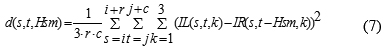
Where Hsm=Maximum shifting at horizontal;
k=Number of image plane component having value 1, 2, 3 respectively; r, c=
number of row and column respectively.
To set a horizontal shift value to measure, how dissimilar pixel analogous to the point t in left image compared among the pixel match with right image. Guided filter is a neighborhood operation; it calculates the output value of pixels statistics of a region in the equivalent spatial neighborhood using guidance image.8 It is used to reduce sharp transitions, de-noising, and incorrect matching in images. Square window size N x N of guided filtering is applied to d(s, t, Hsm). Guided filter is the fast edge-preserving non-approximate linear time filter. The guided filter output g f o at a pixel i is denoted as a weighted average in (8).

Where, I and j are pixel indexes. This filter kernel wij is a function of the guidance image, I and independent of p. The filter is linear with respect to p. This guided image filter assumes linear transformation in a local or centered window Wk the relation between guidance image I and filtering output ᶃƒo can be expressed by

Where Ii indicates gray cost of the pixel i in
the guidance image I. This linear coefficient ak, bk are constant and i wk defines pixel I is in window wk. In eq. (9)
∇ g
f o = a∇I, and ∇ signifies the
gradient therefore g f o has an edge if
Image I has an edge.
To establish the linear coefficients (ak,bk) we require restriction from the filter input p. The linear output g f o as the input p mathematically subtract some surplus components n like noise or textures expressed by

The wk cost function expressed by (11) for minimizing difference of image p and g f o.

Where ϵak2 is regularization term and ϵ is preclude large ak. The linear coefficient ak and bk mathematical calculation as expressed by (12) and (13).
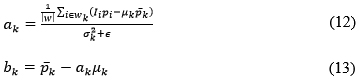
σk2 and μk are the variance and mean respectively of guidance image I in wk, |w| is the number of pixels in wk. p ̅k is the mean of p in wk. By applying guided filter Wij kernel in eq. (14) can be expressed by,
Where μk and σk2
are mean and variance of wk in I. ϵ is a smooth parameter, |w| is the number of
pixels in window with fixed dimension.
For proper horizontal shift value, the minimum starting value is zero. The maximum horizontal shift Hsm is the maximum cost of the pixel in the ground truth divided by the scale factor. Mathematical expressed is shown in (15).

Where Hsm is the specified range of the object, B is the baseline means the distance among the centers of the cameras, f is focal length of the sensor, x pixel size, N maximum disparity value. The window is only shifted along the x direction define as Hsm. To compute the difference, a window is placed fixed at left images, while Hsm is a shift over a finite range in the right image. Further guided filtering outputs the minimum difference value assignment function with a minimum error for each disparity. The minimum error energy g (s, t, Hsm) as the reliable depth estimation for pixel (i, j) of raw depth map is as follow by (16).

The perimeter is the total length of the scene
boundary. It can be measured by tracing the boundary of the object and adding
all the steps of length.
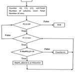
For zero depth map assignment, we count the
disparity map whose disparity is not defined shows flow chart in Figure 2. For
that, we create a map in which the disparity is calculated by its neighbor
pixel in the same column which lies above the said reference pixel. Similarly,
we create another map to compute disparity of said pixel in a downward
direction along the same column. After this process, we get two different
disparity maps among one in above direction and one along the downward
direction. Finally, we compute the finishing disparity map which compares the
prior two different disparities which we obtained earlier.
The filling phase is the key part of our algorithm and completes the final result. Region fill process is based on a set of intersections, dilations and complementation to fill the holes in the image. ‘I’ is the region and connected components. The form an array Xk the similar size as the array include ‘I’ whose elements are 0 (background value), except at each location known to correspond point in every connected component in I, which we set to one foreground value. The purpose is to start with X0 and locate all the linked components by iterative procedure in equation (17)

Where, B – structuring element, Xk = Xk-1 with Xk containing all the connected components of I.
The hybrid (combination of morphological
operators) is erosion, opening, closing and dilation operation by structuring
element neighborhood with precise matrix 1’s and 0’s. In this algorithm we are using random
structure [1 1; 0 0] and [1 1 0; 0 1 0; 0 0 1] etc. Nonlinear spatial filter
known as rank filter is used to decrease the noise and get better the output of
the depth as a grayscale image is applied at the last stage.42
The perimeter measuring process is the next
step to trace the boundary of the scene and adding all the steps of length. In
the map, some pixels have not been assigned value yet so next step is to assign
the value. With the help of perimeter, function assigns the values embedded at
zero value in the map. Here dissimilar pixels are set to unknown. At the end
these are filled using hole filling operation.
Depth maps are generated using 3, 5, 7 and 9 neighborhood size (N x N)
of the median filter at the last of the stage. The median filter reduces the
noise and black specks around the border.9
Results and Discussion
The results of depth are measured for a range
of object located at different distance. Kinect camera has maximum range of
near about four meter and we have calculated different parameter values for 3,
3.5 and 4 meter and the value of cutoff frequency at 3 different radii of 90,
190 and 250 shows in table 1.
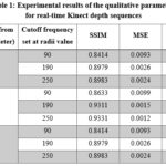 |
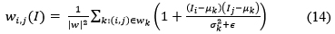
Table 1: Experimental results of the qualitative parameters for real-time Kinect depth sequences
Click here to View Table
|
The object is sets at various sizes and
shapes, so we can confirm the improved efficiency of Kinect based algorithm. Value
of PSNR of the resultant image increases with an increase in cutoff frequency
radii value. The value of MSE decreases with an increase in cutoff frequency
radii value. SSIM value increases with an increase in cutoff frequency redii
value. Results are more appropriate and smooth when the cutoff frequency radii
are increased.10
The better values of SSIM and PSNR are
obtained when the set of radii is 250. The
most of the information in the image will be enclosed in the output at the
distance 3.5 meter. Gaussian low pass
filter has capacity to pass lower frequency component also it will chunk the
higher frequency element. Table 1 show that for lower cutoff frequency and the cost
of statistical parameters is very small as the pass band is very low. It also
shows that as the cutoff frequency increases, the processed image contains more
information and this lead to better values of PSNR, MSE and SSIM.11
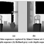 |
Figure 3: Video sequences captured by Kinect Sensor at 4 m distance (a) Gray scale raw depth sequence (b) Refined gray scale depth sequence (Radii value-250)
Click here to View figure
|
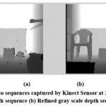 |
Figure 4: Video sequences captured by Kinect Sensor at 3.5 m distance (a) Gray scale raw depth sequence (b) Refined gray scale depth sequence (Radii value-90)
Click here to View figure
|
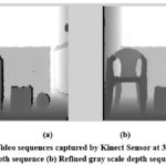 |
Figure 5: Video sequences captured by Kinect Sensor at 3 m distance (a) Gray scale raw depth sequence (b) Refined gray scale depth sequence (Radii value-190)
Click here to View figure
|
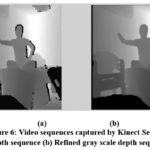 |
Figure 6: Video sequences captured by Kinect Sensor (a) Gray scale raw depth sequence (b) Refined gray scale depth sequence (Radii value-90)
Click here to View figure
|
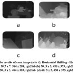 |
Figure 7: The results of cone image (a to d). Horizontal Shifting – Hsm of values (a) 30,7 x 7, 384 x 288, rgb2lab (b) 50, 3 x 3, 450 x 375, rgb2lab (c) 30, 3 x 3, 484 x 383, rgb2lab (d) 60, 5 x 5, 450 x 375, rgb2lab
Click here to View figure
|
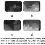 |
Figure 8: The results of cone image (a to d). Horizontal Shifting – Hsm of values (a) 30,7 x 7, 384 x 288, rgb2xyz (b) 50, 3 x 3, 450 x 375, rgb2xyz (c) 30, 3 x 3, 484 x 383, rgb2xyz (d) 60, 5 x 5, 450 x 375, rgb2xyz
Click here to View figure
|
The speed of processing the algorithm diverges
with the numbers of invalid pixels and numbers of acquired frames. The average
time of the algorithm is 35 seconds per 300 frames. This estimated time of one
frame is 0.11 second per frame-SPF. This method generates visibly clear and
accurate filling of hole. The post-processing step corrects and sharpens the
boundary of the objects of the depth map and makes sure local depth smoothness
the object. Experimental result shows that the random error of depth
measurement increases when the distance between the scene and the sensor
increases, ranging from a few millimeters to about 4 meter.14 Stereo
matching algorithm uses different number of windows of different sizes to make
a fair evaluation shown in Figure 7 and 8. The computation of time of the
algorithm increases with an increase in window size.11-13
Conclusion
The depth quality is enhanced by depth renovation
in frequency domain technique, fills the holes in depth sequences, 2-D spatial
filtering and combination of morphological operation. An experiment result
demonstrates the quality of our projected method is better than preceding research
work. Our algorithm generates noiseless, efficient, reliable and smooth depth
sequence. This algorithm with Kinect sensor works in dark region.
We conclude
that for upper window sizes the performance of the filter deteriorates as
compared with lower window sizes it is because in low window size the number of
elements in windows is dedicated and the filter costs are near which gives a
mean value remove the noise. But filter window increases the elements of filter
also increase that gives a degree of noise remove but additional a value of
noise in the filtered image. Guided and nonlinear spatial filters decrease the
noise and improve the results of the depth images. The experimental results
show that guided and nonlinear spatial filters give optimum and best quality results
for all noise mass in 3 x 3 window size.
As window size increases the SSIM increases.
The values of SSIM are better in quality in rgb2xyz conversion as compared to
rgb2lab. The depth maps recovered by our algorithm are closed to the ground
truth data.
Acknowledgements
The authors wish to express their gratitude to
the Principal and Dean, College of Agricultural Engineering and Technology,
Junagadh Agricultural University, Junagadh India for providing valuable
guidance and other facilities for preparation of this manuscript.
Funding
This research received no external funding.
Conflict of Interest
All the authors
declare that there is no conflict of interest.
References
Conference
Papers
- Jianbo Jiao, Ronggang Wang, “Local stereo matching with improved matching cost and disparity refinement,” IEEE Computer Society, 1070-986X/14/2014, pp.16-27.
CrossRef - S. Mukherjee, R. M. Guddeti, “A hybrid algorithm for disparity calculation from sparse disparity estimates based on stereo vision,” IEEE, 978-1-4799-4665-5/14/ 2014.
- He, K., Sun, J. and Tang, X., 2010, September. Guided image filtering. In European conference on computer vision (pp. 1-14). Springer Berlin Heidelberg.
CrossRef - K. Rao, Joohee Kim, “Refinement of Depth Maps Generated By Low-Cost Depth Sensors,” 978-1-4673-2990-3, pp. 355-358, ISOCC, IEEE, 2012.
Books
- Gonzalez, R.C. and Woods, R.E., 2008. Digital image processing. Nueva Jersey.
- Jain, A.K., 1989. Fundamentals of digital image processing. Prentice-Hall, Inc..
Journal
Papers
- Xiaoyan Hu, Philippos Mordohai, “A quantitative evaluation of confidence measures for stereo vision”, IEEE transactions on pattern analysis and machine intelligence, 0162-8828/12, vol. 34, no. 11, November 2012, pp. 2121-2133.
CrossRef - Kaiming He, Jian Sun, “Guided image filtering,” IEEE Transactions on Pattern Analysis and Machine Intelligence, Vol. 35, 2013.
CrossRef - Ashish M. Kothari, Ved Vyas Dwivedi, “Performance Analysis of Digital Video Watermarking using Discrete Cosine Transform,” International Journal of Electrical and Computer Engineering Systems Issues Vol. 2, Number 1, pp. 11-16 2011
- Ling Shao, “Computer Vision for RGB-D Sensors: Kinect and Its Applications”, IEEE Transactions On Cybernetics, Vol. 43, No. 5, October 2013.
CrossRef - T. Mallick, “Characterizations of Noise in Kinect Depth Images: A Review,” IEEE Sensors Journal, VOL. 14, NO. 6, pp. 1731-1740, 2014.
CrossRef - Yongjoo Cho, Kiyoung Seo, Kyoung Shin Park, “Enhancing Depth Accuracy on the Region of Interest in a Scene for Depth Image Based Rendering”, KSII Transactions On Internet And Information Systems Vol. 8, No. 7, July. 2014
CrossRef - Ke-Yu Lin and Hsueh-Ming Hang, “Depth Map Enhancement On Rgb-D Video Captured By Kinect V2” Proceedings, APSIPA Annual Summit and Conference 2018 ,12-15 November 2018, Hawaii, 978-988-14768-5-2.
CrossRef
Web Resources
- Kinect sensor specifications, [Online], Available: http://www.microsoft.com.

This work is licensed under a Creative Commons Attribution 4.0 International License.